The main task of ventilation systems is to take in, heat or cool the fresh air, and to expel the polluted air. Besides this task, Fire escapes and emergency elevators will be used for evacuation purposes, positive pressure is needed to accommodate clean air, and therefore pressurization systems are used in the event of a possible fire in buildings.
Smoke resulting from the fire inside the building can be transported to non-fire areas through ventilation ducts. Fire which is outside the building; It is also possible for the smoke to be taken into the building by the air handling units or the pressurization system.
To prevent this situation which is extremely dangerous and serious consequences, it is importance to place detectors which provide early detection in the ventilation duct.
One of the most preferred device is the UG-7 ventilation Sampling Device. This is because the smoke detection of the device is sensitive and reliable. Besides to detection of fire, Fire dampers and other devices must be controlled so that smoke does not disperse into the air ducts from inside and outside the building.
In case of detectors installed in the duct with UG-7 Superflow Air Duct Sampling Unit, heating, smoke can be easily detected when the ventilation or air conditioning (HVAC) fan motor overheats, it is commanded relative relays according to fire scenario.
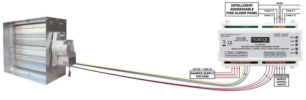
Thanks to these commands, the power to the fan motor is cut off, and the fire dampers can be brought to the closed position to prevent the smoke from reaching other areas fed by the relevant channel.
Smoke Detection and Management in Ventilation Ducts
Fire and gas detection systems, which are obligatory to be installed in buildings according to the regulation, and duct type smoke detectors installed in ventilation ducts are located in the same loop line and all necessary controls are made according to cause-effect scenarios through relay modules.
There is extremely important to follow the guidelines of the standards and regulations. For example , According to fire guidelines of the standards, when the duct direction changes, a duct type smoke detector should be used at a distance of 5 times hydraulic duct diameter of this change point. If damper is close to filter device, this ratio should be 3 times higher.
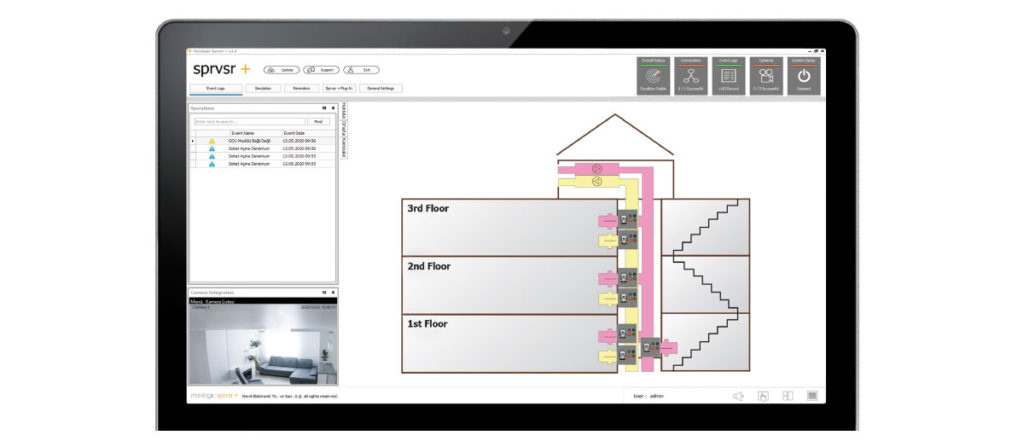
Figure 1. Example of Ventilation Duct Smoke Detector Installation
According to the standards on the Installation of Air Conditioning and Ventilation Systems; The following items should be considered when determining the positions of duct type smoke detectors to be used in air distribution systems.
1- For duct installations to automatically stop supply fans in systems above 2000 cfm ; cfm: cubic feet per minute; Duct type smoke detectors should be installed at a suitable point in the main supply duct under the filters.
2- For systems above 15,000 cfm; Additional duct type detectors are required at the common return entry point in the return system of each floor
3- To detect whether smoke is drawn into the system from outside of buildings, Duct type detectors are required close to the outdoor air supply. Thanks to warning signal coming from Duct type detectors, The outside air damper of the HVAC system will be closed.
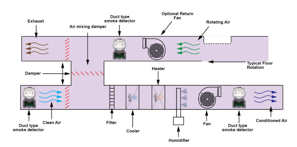
Figure 2. Duct Type Smoke Detection in Ventilation System Central Units
In example of HVAC system, when it detects smoke in any channel; By turning off the fan system and switching all the dampers shown to off position, it will be possible to prevent the distribution of smoke over the air handling unit to unaffected areas of a building.
– As alternative method, air supply fan is turned off, fan continues to run, the outside air damper and the air mixing damper are closed. At those moment, if exhaust damper is opened, smoke will be occured.
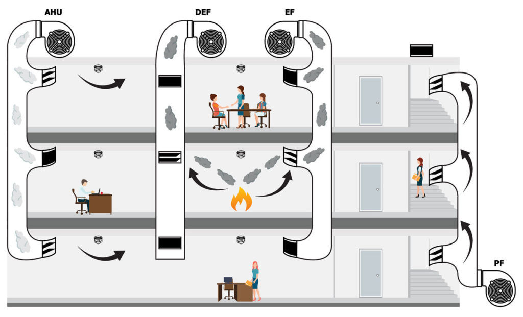
Smoke Detection and Management in Pressurization Ducts
Fire stairs and emergency elevators which are used for emergency evacuation in buildings; The presence of smoke is prevented by providing controlled overpressure with permanently installed pressure devices. Smoke evacuation is important in an emergency situtation for fire exit and rescue point. When Pressure Sytems are designed,
– When the doors are closed, the pressure difference between the protected and unprotected area ≤ 100 N corresponds to the maximum door opening force.
– When the doors are opened, air flow has to be between 1 m/s and 2 m/s for air exit channel.